AWR LTCC Process Library (PDK)
We can speed up your LTCC layout process and make you LTCC design stable, more transparent and automated, add simulation capabilities (schematic, EM, Extraction) verify models of components, add DRC and improve order process.
AWR LTCC Process Library Could be implemented in existing or New Project as a PDK (Process Development Kit)

LTCC Development Flow
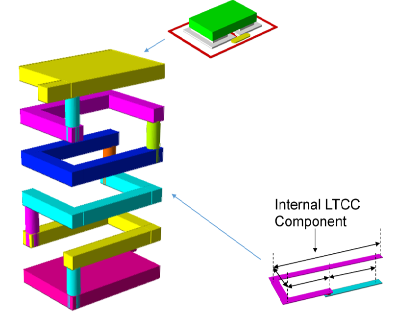 LTCC LC resonance circuit
Adds Support of Such global features During Project Development:
-
Additional Components
-
Additional Scripts
-
Global Project Settings
-
Schematic Automation
-
Layout Automation
-
Simulation Automation
-
Design Rules Check Automation
-
Manufacturing Automation
-
LTCC PDK – Allow You to Use Such Automation Features Directly for Your
LTCC Process (Number of Layers, Materials…)
-
Possibility to Use Combine Process – LTCC + Mount ComponentPackage for EM Simulation
Additional Components:
-
Allow you to use needed symbols in the schematic and footprints for LTCC External LTCC Components
Additional Scripts:
-
Allow you to use some features your design as:
-
Design Features (e.g. Automatic VIA Placing or Automatic Graph Generation)
-
External Features – (e.g. GERBER Importer – Allow to Import Some Needed Parts from Another Software )
-
Many Others
-
-
Global Project Settings:
Includes Such Important General Setting As:
-
Frequency Settings
-
Schematic and EM Global Simulation Settings
- < >
Result Grasps
-
LTCC and Metal Material Properties
-
Setting Right Names for all Needed Objects
-
And Many Others
Schematic Automation:
-
Additional Components Symbols
-
Schematic Simulation Settings
-
Layout to EM Extraction Settings (Stack-Ups)
-
Schematic and EM Local Simulation Settings
-
And Many Others
Layout Automation:
-
Additional Components – Footprints
-
2D Layers Settings
-
3D Layers Settings
-
Process Layers Settings
-
Drills and VIA-s Settings
-
Routing Settings
And Many Others

EM Co-Simulation of deigned structure
-
Automatic extraction to different simulators of structure parts
-
No manual creating of EM is required
-
MOM, FEM and circ.extraction methods are available
-
-
Requires minimum attention of customer
-
Fully integrated to design process
-
Supports HFSS, CST engines and other
Co-Simulation of Structure
-
Includes parasitic effects
High correlation with measurement
Design Rules Check Automation:
-
Possibility to Use Different
-
Possibility to use Different Precision setting for one manufacturer
Design Rules Check Automation:
-
Pick and Place Data (P&P)
-
Gerber Files + Drill List (GERBER)
-
Built of Materials (BOM)
-
Most LTCC Devices and, which we Support:
Devices
- Filters
- Mixers
- Baluns
- Matching Circuits
- Dulexers
We can design any additional
feature using standard AWR capabilities or using
Visual Basic Scripts.
For all the questions, please contact us info@ag-rf-engineering.de